


This month, Pierson Wireless will address a number of topics related to the best practices in the design and implementation of Emergency Responder Communication Enhancement Systems (ERCES) – also known as Public Safety DAS (Distributed Antenna System).
The single most important reason Public Safety DAS exist and are necessary is to ensure critical in-building communications between members of first responder teams that can mean the difference between life and death as they coordinate and execute emergency response tactics.
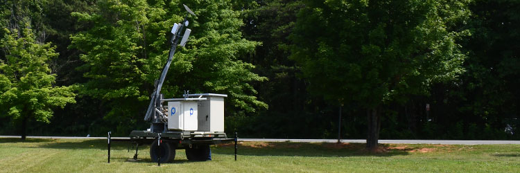
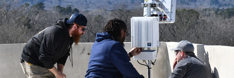
First responders coordinate efforts via radio signals broadcast within government-mandated frequency ranges, normally in the VHF, UHF, 700, and 800 MHz bands. A Public Safety DAS leverages a donor antenna to receive RF transmissions from public safety network towers. In turn, those signals are collected, amplified, and rebroadcast within the structure via a distributed network of antennas.
The preponderance of steel, concrete, and low-emissivity (Low-E) glass in modern construction creates many challenges for a reliable signal in large venues or multiple-level buildings. The density of materials, coupled with the square footage within the structure, makes it difficult for first responder radio signals to penetrate and populate the entirety of the space. As a result, municipalities are updating codes to make the presence of a Public Safety DAS mandatory and a requirement of occupancy.
Today’s look at best practices utilized by the Pierson Wireless Public Safety team takes a look at redundancy in a public safety communications system solution.
REDUNDANCY IN ERCES
Redundancy ensures the reliability, availability, and continuity of critical operations. Implementing redundant systems can minimize downtime and mitigate the risks of hardware failures or disruptions. However, it adds an extra cost to the initial system for equipment that may not be required or utilized.
The current Federal Communications Commission (FCC), National Fire Protection Association (NFPA), and International Fire Code (IFC) codes do not require redundancy in Emergency Responder Communication Enhancement Systems – also known as Public Safety DAS – except for the power source. The solutions below reference possible ways to achieve system-level redundancy should it be desired.
Redundancy in an ERCES can be done in multiple ways. The majority of the methods of redundancy utilize only certain parts to be duplicated in an ERCES. These methods are to solve the issues of signal booster failure, donor antenna failure, and donor site failure.
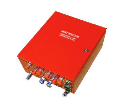
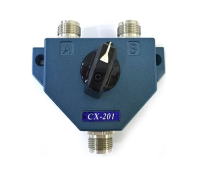
The most effective solutions utilize a component called a radio frequency (RF) switch. An RF switch is a device that accepts two inputs and allows for one to be selected for circuit completion. An RF switch can be manual and require a physical turning of the switch to swap between the two signal paths, or it can be automatic and switch between the input signals when it detects a malfunction. An automatic switch is the best way to ensure maximum system performance without needing a physical change of the switch position and RF signal source.

Automatic RF Switch

Manual RF Switch
|
|
| Automatic RF Switch | Manual RF Switch |

Full system redundancy is the installation of two complete ERCES in a facility. This method doubles the cost of the ERCES, becomes difficult to implement, is very rarely used, and is not recommended. This also requires that only one of the systems is operating at any given time to prevent issues with noise, oscillation, and interference and requires an automated control to determine when to switch to the secondary system from the primary.

Donor antenna-only redundancy is the installation of two donor antennas and an RF switch. The switch is placed between the donor antennas and the signal booster (also known as a bi-directional antenna, or BDA). This method adds the additional cost of the secondary donor antenna, donor coaxial cable, and RF switch. This solution is the least difficult to implement and provides donor site redundancy but offers no resolution in the case of booster failure.

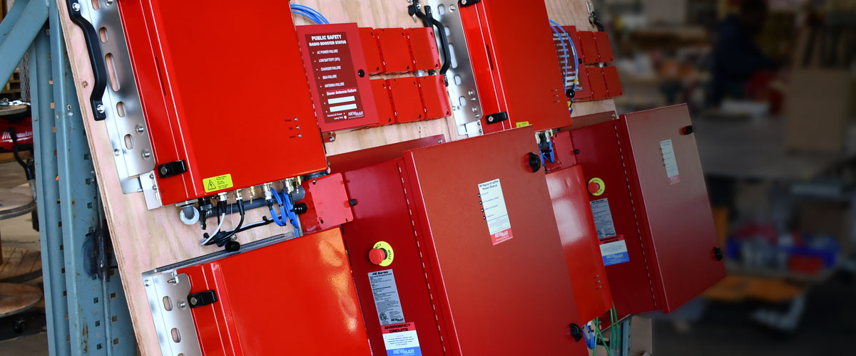
Signal booster-only redundancy is the installation of two signal boosters using a signal donor antenna and two RF switches. The signal boosters are connected to the passive systems, donor, and server via an RF switch. This method has the additional cost of two RF switches and a secondary signal booster with battery backup. This solution provides for booster failure but does not give donor antenna or donor site redundancy.

Signal booster and donor antenna redundancy is the installation of two signal boosters, each individually fed by its donor antenna and an RF switch to connect to the passive serving system. This method has the additional cost of an RF switch, a secondary signal booster with battery backup, a donor coaxial cable, and a secondary donor antenna. This solution provides adequate redundancy for the ERCES for booster, donor antenna, and donor site failure.
Again, this system redundancy level is neither common nor part of the current national codes, but the methods offered here come at different price points. It is recommended that the Authority Having Jurisdiction (AHJ) is contacted to determine what options are best suited to fulfill the requirements.
Pierson Wireless is an industry leader in ERCES and Public Safety DAS solution design, implementation, and system monitoring. To learn more about our expertise in the space or to schedule a consultation, visit our Public Safety resource page.


Leave A Comment